Deprecated: Creation of dynamic property WP_Term::$cat_ID is deprecated in /var/www/twodee/blog/wp-includes/category.php on line 378
Deprecated: Creation of dynamic property WP_Term::$category_count is deprecated in /var/www/twodee/blog/wp-includes/category.php on line 379
Deprecated: Creation of dynamic property WP_Term::$category_description is deprecated in /var/www/twodee/blog/wp-includes/category.php on line 380
Deprecated: Creation of dynamic property WP_Term::$cat_name is deprecated in /var/www/twodee/blog/wp-includes/category.php on line 381
Deprecated: Creation of dynamic property WP_Term::$category_nicename is deprecated in /var/www/twodee/blog/wp-includes/category.php on line 382
Deprecated: Creation of dynamic property WP_Term::$category_parent is deprecated in /var/www/twodee/blog/wp-includes/category.php on line 383
Deprecated: Creation of dynamic property WP_Term::$cat_ID is deprecated in /var/www/twodee/blog/wp-includes/category.php on line 378
Deprecated: Creation of dynamic property WP_Term::$category_count is deprecated in /var/www/twodee/blog/wp-includes/category.php on line 379
Deprecated: Creation of dynamic property WP_Term::$category_description is deprecated in /var/www/twodee/blog/wp-includes/category.php on line 380
Deprecated: Creation of dynamic property WP_Term::$cat_name is deprecated in /var/www/twodee/blog/wp-includes/category.php on line 381
Deprecated: Creation of dynamic property WP_Term::$category_nicename is deprecated in /var/www/twodee/blog/wp-includes/category.php on line 382
Deprecated: Creation of dynamic property WP_Term::$category_parent is deprecated in /var/www/twodee/blog/wp-includes/category.php on line 383

And here is my first attempt at modeling them using Madeup’s dowel command with rounded bends:
Notice the hole in the middle. Given how the rounding is implemented, I was not able to remove it. You can bet that I was haunted by that hole. I took some time to design a new solidifier so that I could create this shape. The solidifier is called table. One feeds it a list of cross sections, all of the same cardinality, and the cross sections are connected together.
The shape generated by table has no hole.
Someday soon I’ll have a more general loft solidifier, which will allow cross sections of different cardinalities.
Deprecated: Creation of dynamic property WP_Term::$cat_ID is deprecated in /var/www/twodee/blog/wp-includes/category.php on line 378
Deprecated: Creation of dynamic property WP_Term::$category_count is deprecated in /var/www/twodee/blog/wp-includes/category.php on line 379
Deprecated: Creation of dynamic property WP_Term::$category_description is deprecated in /var/www/twodee/blog/wp-includes/category.php on line 380
Deprecated: Creation of dynamic property WP_Term::$cat_name is deprecated in /var/www/twodee/blog/wp-includes/category.php on line 381
Deprecated: Creation of dynamic property WP_Term::$category_nicename is deprecated in /var/www/twodee/blog/wp-includes/category.php on line 382
Deprecated: Creation of dynamic property WP_Term::$category_parent is deprecated in /var/www/twodee/blog/wp-includes/category.php on line 383
Deprecated: Creation of dynamic property WP_Term::$cat_ID is deprecated in /var/www/twodee/blog/wp-includes/category.php on line 378
Deprecated: Creation of dynamic property WP_Term::$category_count is deprecated in /var/www/twodee/blog/wp-includes/category.php on line 379
Deprecated: Creation of dynamic property WP_Term::$category_description is deprecated in /var/www/twodee/blog/wp-includes/category.php on line 380
Deprecated: Creation of dynamic property WP_Term::$cat_name is deprecated in /var/www/twodee/blog/wp-includes/category.php on line 381
Deprecated: Creation of dynamic property WP_Term::$category_nicename is deprecated in /var/www/twodee/blog/wp-includes/category.php on line 382
Deprecated: Creation of dynamic property WP_Term::$category_parent is deprecated in /var/www/twodee/blog/wp-includes/category.php on line 383
I’m struggling to find a name for this shape.
Last week I rewrote my dowel generation algorithm in Madeup, so my subconscious mind informed me that this shape is a dowel. My conscious mind set to modeling it. My first draft just traced out the path from one block to the next using turtle geometry:
The code makes the repetition visible. I condensed it with this loop:
My version of the shape has a hole in the middle. This is necessary given the way I round out the bends. If I shrink it any further, the bend geometry starts to degenerate. You can see this for yourself by changing the distance of the move commands.
Deprecated: Creation of dynamic property WP_Term::$cat_ID is deprecated in /var/www/twodee/blog/wp-includes/category.php on line 378
Deprecated: Creation of dynamic property WP_Term::$category_count is deprecated in /var/www/twodee/blog/wp-includes/category.php on line 379
Deprecated: Creation of dynamic property WP_Term::$category_description is deprecated in /var/www/twodee/blog/wp-includes/category.php on line 380
Deprecated: Creation of dynamic property WP_Term::$cat_name is deprecated in /var/www/twodee/blog/wp-includes/category.php on line 381
Deprecated: Creation of dynamic property WP_Term::$category_nicename is deprecated in /var/www/twodee/blog/wp-includes/category.php on line 382
Deprecated: Creation of dynamic property WP_Term::$category_parent is deprecated in /var/www/twodee/blog/wp-includes/category.php on line 383
Deprecated: Creation of dynamic property WP_Term::$cat_ID is deprecated in /var/www/twodee/blog/wp-includes/category.php on line 378
Deprecated: Creation of dynamic property WP_Term::$category_count is deprecated in /var/www/twodee/blog/wp-includes/category.php on line 379
Deprecated: Creation of dynamic property WP_Term::$category_description is deprecated in /var/www/twodee/blog/wp-includes/category.php on line 380
Deprecated: Creation of dynamic property WP_Term::$cat_name is deprecated in /var/www/twodee/blog/wp-includes/category.php on line 381
Deprecated: Creation of dynamic property WP_Term::$category_nicename is deprecated in /var/www/twodee/blog/wp-includes/category.php on line 382
Deprecated: Creation of dynamic property WP_Term::$category_parent is deprecated in /var/www/twodee/blog/wp-includes/category.php on line 383
There are a few significant changes in this new Madeup. In this update, I will focus on one: positional parameters are no longer a thing. In the old Madeup, you could generate a dowel with this code:
Positional parameters are ordered lists of raw data sent to a function. Here, the positional parameters are 10 and 45. These actual parameters are implicitly mapped to the formal parameters of dowel merely by their order of appearance in the call. I think the implicitness of this serial mapping is unfriendly to learners. A first-time reader of code with positional parameters is unlikely to understand it. What do 10 and 45 mean?
The documentation reveals that the first parameter is maxBend, which is used to smooth sharp bends, and the second parameter is twist, which rotates the polygonal cross section of the dowel about its axis. The gulf between the documentation and the editor is not small. The folks who understand positional parameters are the ones who have memorized the API. I want Madeup to be welcoming to those who haven’t.
In the new Madeup, you generate a dowel with named parameters:
The names are not optional. This reflects my new philosophy of programming: everything should be named.
Named parameters have benefits. They hint at the meaning of the formerly magic numbers. They can appear in any order, freeing the programmer from having to memorize extraneous details and freeing me from having to lock down the interface of builtin functions in the name of backward compatibility.
Named parameters also have a cost: they make the code longer and more verbose. I want to mitigate this cost, and following are a few of my plans to do so.
Defaults
Consider the following program, which renders an L-shaped bracket.
Often I build 3D objects in the XY plane, and explicitly setting z = 0 in the moveto commands as I do here feels like a waste of time. Therefore I have made a decree. When a parameter has a reasonable default value, that default may be defined in the function definition. A programmer who wishes to employ that default value can omit the parameter from the call. In the following version of the code, we employ the defaults for z, nsides, and twist.
No Name = Name
Consider the following program, which renders a row of cubes.
I think that x = x is silly. Therefore I have made a decree. When a variable is passed as an actual parameter to a formal parameter of the same name, the assignment syntax for the parameter is not necessary. It can be written in shorthand as just the shared name. In the following version of the code, we have variables for x, y, and z and our moveto call is much more concise.
Implicit Parameters
We can take that shorthand a step further. If a variable with the same name as a formal parameter is in scope, then we can automatically transfer it along as a parameter—leaving it out of the function call altogether. These are called implicit parameters.
In this program, we implicitly pass y to three moveto calls.
Implicit parameters allow us to factor out repetitive code. We set the shared y parameter just once, leaving the moveto calls uncluttered. We clearly see the differences between the calls: the varying x values.
Multi-parameters
Suppose we have a position p. We could render a sphere centered on this position with the following program.
The syntax here feels clumsy. I have to break down the list manually and spread it across the x, y, and z parameters. How shall we fix this? I could just have moveto accept a list instead of three separate parameters, but I don’t want lists to be a prerequisite for building interesting shapes in Madeup. I could add another version of moveto that accepted a list. Or I could give the existing moveto an alternative xyz or position parameter. Neither of these feels general enough. Therefore I have decreed that we need a splatting syntax for assigning multiple parameters at once from a list.
In this version of the program, we automatically decompose p and pass its elements as values for x, y, and z.
]]>
Deprecated: Creation of dynamic property WP_Term::$cat_ID is deprecated in /var/www/twodee/blog/wp-includes/category.php on line 378
Deprecated: Creation of dynamic property WP_Term::$category_count is deprecated in /var/www/twodee/blog/wp-includes/category.php on line 379
Deprecated: Creation of dynamic property WP_Term::$category_description is deprecated in /var/www/twodee/blog/wp-includes/category.php on line 380
Deprecated: Creation of dynamic property WP_Term::$cat_name is deprecated in /var/www/twodee/blog/wp-includes/category.php on line 381
Deprecated: Creation of dynamic property WP_Term::$category_nicename is deprecated in /var/www/twodee/blog/wp-includes/category.php on line 382
Deprecated: Creation of dynamic property WP_Term::$category_parent is deprecated in /var/www/twodee/blog/wp-includes/category.php on line 383
Deprecated: Creation of dynamic property WP_Term::$cat_ID is deprecated in /var/www/twodee/blog/wp-includes/category.php on line 378
Deprecated: Creation of dynamic property WP_Term::$category_count is deprecated in /var/www/twodee/blog/wp-includes/category.php on line 379
Deprecated: Creation of dynamic property WP_Term::$category_description is deprecated in /var/www/twodee/blog/wp-includes/category.php on line 380
Deprecated: Creation of dynamic property WP_Term::$cat_name is deprecated in /var/www/twodee/blog/wp-includes/category.php on line 381
Deprecated: Creation of dynamic property WP_Term::$category_nicename is deprecated in /var/www/twodee/blog/wp-includes/category.php on line 382
Deprecated: Creation of dynamic property WP_Term::$category_parent is deprecated in /var/www/twodee/blog/wp-includes/category.php on line 383
Deprecated: Creation of dynamic property WP_Term::$cat_ID is deprecated in /var/www/twodee/blog/wp-includes/category.php on line 378
Deprecated: Creation of dynamic property WP_Term::$category_count is deprecated in /var/www/twodee/blog/wp-includes/category.php on line 379
Deprecated: Creation of dynamic property WP_Term::$category_description is deprecated in /var/www/twodee/blog/wp-includes/category.php on line 380
Deprecated: Creation of dynamic property WP_Term::$cat_name is deprecated in /var/www/twodee/blog/wp-includes/category.php on line 381
Deprecated: Creation of dynamic property WP_Term::$category_nicename is deprecated in /var/www/twodee/blog/wp-includes/category.php on line 382
Deprecated: Creation of dynamic property WP_Term::$category_parent is deprecated in /var/www/twodee/blog/wp-includes/category.php on line 383
Deprecated: Creation of dynamic property WP_Term::$cat_ID is deprecated in /var/www/twodee/blog/wp-includes/category.php on line 378
Deprecated: Creation of dynamic property WP_Term::$category_count is deprecated in /var/www/twodee/blog/wp-includes/category.php on line 379
Deprecated: Creation of dynamic property WP_Term::$category_description is deprecated in /var/www/twodee/blog/wp-includes/category.php on line 380
Deprecated: Creation of dynamic property WP_Term::$cat_name is deprecated in /var/www/twodee/blog/wp-includes/category.php on line 381
Deprecated: Creation of dynamic property WP_Term::$category_nicename is deprecated in /var/www/twodee/blog/wp-includes/category.php on line 382
Deprecated: Creation of dynamic property WP_Term::$category_parent is deprecated in /var/www/twodee/blog/wp-includes/category.php on line 383
Deprecated: Creation of dynamic property WP_Term::$cat_ID is deprecated in /var/www/twodee/blog/wp-includes/category.php on line 378
Deprecated: Creation of dynamic property WP_Term::$category_count is deprecated in /var/www/twodee/blog/wp-includes/category.php on line 379
Deprecated: Creation of dynamic property WP_Term::$category_description is deprecated in /var/www/twodee/blog/wp-includes/category.php on line 380
Deprecated: Creation of dynamic property WP_Term::$cat_name is deprecated in /var/www/twodee/blog/wp-includes/category.php on line 381
Deprecated: Creation of dynamic property WP_Term::$category_nicename is deprecated in /var/www/twodee/blog/wp-includes/category.php on line 382
Deprecated: Creation of dynamic property WP_Term::$category_parent is deprecated in /var/www/twodee/blog/wp-includes/category.php on line 383
A few weeks ago, my wife asked me if I thought our sons would study computer science. I told her that I hoped to teach them enough of it at home that they’d be freed up to study something else.
I really do like my discipline, but I love more the things that my children, my students, and I can make with it. The past few years, I have been searching for ways to make computer science less virtual and more physical, more integrated in the world around us. Our agenda for today is to demonstrate three projects that support my mission of making computer science less virtual.
Computational Making
Schools left and right, politically and geographically, are establishing makerspaces, buying up 3D printers and laser cutters, and getting their students designing and building real things. The students are making. This sounds great. However, if you talk to the teachers and librarians who are staffing these makerspaces, you will hear about the many kids who are just downloading other people’s 3D models and design files from Thingiverse and fabricating those.
This happens for a couple of reasons. First, its part of the maker ethos to share what one has made. Second, learning to model in 2D and 3D is time-consuming and doesn’t really fit well into an already crowded school curricula. I think computer science can fix this. Instead of just plain making, we need computational making.
We hear a lot these days about computational thinking. There’s little agreement about what skills and concepts make up computational thinking, and it has come to be used as a way to invoke the idea of computer science but subtract out or downplay programming. I needed a term to invoke the idea of creating but with programming added in. That is computational making, which I define as a creative process
- guided by algorithms and data
- carried out in a parametric design space
- with a physical output.
Let’s now look at some tools I’ve been building to facilitate computational making.
Madeup
The first tool is Madeup, a programming language for making things up—literally. It is very much modeled after the drawing mechanics of Seymour Papert’s Logo from the 1980s, but extended to three dimensions. Madeup, like Logo, is meant to make learning geometry an interactive experience. Instead of imposing a grand coordinate system over all space, the programmer uses a coordinate system relative to the avatar on the screen. Logo’s avatar was a turtle, and Papert called this way of thinking about space turtle geometry. Let’s see it at work in an example. We’ll code a rupee from the Legend of Zelda games.
For those of you who have been spending your time elsewhere, rupees look like this:

We will program the cross section of one of these. Imagine that we cut one right down the middle. What shape would we see? An elongated hexagon. Let’s write Madeup code to trace out the top half of the hexagon, like so:
Next we revolve that cross section around the x-axis, sampling the surface or revolution just six times to produce the hexagonal structure:
And finally we stretch it a bit vertically:
What if want to make a sharper bevel? We must change the angle we turn. Instead of 45, let’s try 30:
Whoops. We’ll need to change the peak angle too. But to what? Some experimentation leads us to 120:
But we can do better than experiment. Why is it 120? Because all told, we are turning back the direction we came, which is 180 degrees. We burn 30 of those up on the first yaw and 30 on the third yaw. That leaves 120 left for the middle yaw. Now we can generalize this and turn the angle into a parameter:
Madeup is a fully-featured programming language. It supports conditionals, loops, variables, functions, and arrays. There are many ways to turn a path into a solid. We’ve seen revolve, but there’s also dowel. Let’s make a chain link:
Let’s see a few more examples.
This perimeter of this gear is extruded and a hole is subtracted from its center:
The Madeup editor also supports a blocks programming interface, and one can (mostly) switch back and forth between text and blocks.
How does Madeup make computer science less virtual? The model can be printed on a 3D printer or embedded in a game engine.
I spent the last year
Twoville
The second project I’d like to share you has one less than dimension than Madeup. Twoville’s purpose is to help programmers build 2D scalable vector graphics (SVG) files that can be fed into a laser or vinyl cutter.
Let’s make another jewel, a diamond. Since we’re in 2D, we’ll just create the profile of a diamond. We start with a square, but rotate it a bit:
Twoville tends to be a very declarative language, as we’re often just setting properties. To ease the syntactic burden of setting a sequence of properties, I added in the scoping function with:
We want to chop off the top, so we overlay another rectangle across it:
To remove the red rectangle, we create a cutout object that serves as a mask:
A similar approach can be used to make a phone:
Like Madeup, Twoville supports conditionals, loops, functions, and arrays. I used functions to abstract out the droplet shapes of this logo that I walked by everyday in Brisbane, Australia, during the first half of my sabbatical:

If you’ve done anything with 3D printing in schools, you will have encountered the slowness of the technology. Models take a long time to print, and the machines need minding. 3D printing doesn’t scale well to large groups of students. Vinyl and laser cutters are much faster, and I think Twoville will better accommodate the time-limited summer camps and workshops I’ve been putting on back home.
Deltaphone
The last project I’d like to share has a less touchable output. It also has one less dimension than Twoville. I’m losing dimensions as I get older. It must be a case of “dimentia.” Deltaphone is my exploration of applying the idea of turtle geometry to music. Instead of thinking about music as a sequence of absolute positions on the staff, we think of a song in Deltaphone as a sequence of changes or deltas between one note and the next.
Let’s compose a little song to see how it works.
Deltaphone supports variables, conditionals, loops, and functions. The output of Deltaphone is a score.
This project is only a few months old, and I don’t know if it has a future or not. I need to find a music teacher who doesn’t feel threatened by technology and who can help me shape it into a tool to explore music theory and composition.
Conclusion
These are three projects that I have been developing to make computer science less virtual, to fit it into the everyday worlds of objects and music.
Educational psychologists argue about whether its better to learn a subject in a contextualized or decontextualized manner. Contextualized learning situates concepts in a themed narrative, like robotics or game development. Decontextualized learning happens when there is no overarching narrative.
Neither approach is perfect. We often rely on the context to engage students. The danger of contextualized learning is that learners may not see that concepts transfer to other contexts. For example, someone who has written an algorithm to determine the winner from a collection of players may not see that a very similar algorithm can be used to find the largest file in a directory. The danger of decontextualized learning is that that learners may not see that concepts transfer anywhere.
While this debate is important for educators to consider, I’d like turn it around a bit. What if we embedded computer science in a context not to improve the learning of computer science, but to improve the learning of the context? If the folks using these tools become better makers, mathematicians, and musicians, then my goal will be met.
]]>Deprecated: Creation of dynamic property WP_Term::$cat_ID is deprecated in /var/www/twodee/blog/wp-includes/category.php on line 378
Deprecated: Creation of dynamic property WP_Term::$category_count is deprecated in /var/www/twodee/blog/wp-includes/category.php on line 379
Deprecated: Creation of dynamic property WP_Term::$category_description is deprecated in /var/www/twodee/blog/wp-includes/category.php on line 380
Deprecated: Creation of dynamic property WP_Term::$cat_name is deprecated in /var/www/twodee/blog/wp-includes/category.php on line 381
Deprecated: Creation of dynamic property WP_Term::$category_nicename is deprecated in /var/www/twodee/blog/wp-includes/category.php on line 382
Deprecated: Creation of dynamic property WP_Term::$category_parent is deprecated in /var/www/twodee/blog/wp-includes/category.php on line 383
Deprecated: Creation of dynamic property WP_Term::$cat_ID is deprecated in /var/www/twodee/blog/wp-includes/category.php on line 378
Deprecated: Creation of dynamic property WP_Term::$category_count is deprecated in /var/www/twodee/blog/wp-includes/category.php on line 379
Deprecated: Creation of dynamic property WP_Term::$category_description is deprecated in /var/www/twodee/blog/wp-includes/category.php on line 380
Deprecated: Creation of dynamic property WP_Term::$cat_name is deprecated in /var/www/twodee/blog/wp-includes/category.php on line 381
Deprecated: Creation of dynamic property WP_Term::$category_nicename is deprecated in /var/www/twodee/blog/wp-includes/category.php on line 382
Deprecated: Creation of dynamic property WP_Term::$category_parent is deprecated in /var/www/twodee/blog/wp-includes/category.php on line 383
Do you know what they do? They are most assuredly not magic. Here, let’s rename the variables, and you can try again:
These equations generate coordinates across the surface of a sphere. It’s hard to tell, but they compactly apply polar coordinate conversions twice. Let’s derive them one step at a time.
First, let’s say the south pole has a latitude of -90 degrees, and the north pole has a latitude of +90 degrees. Let’s traverse this span of latitudes in 10-degree ticks:
I’ll be playing with the scale a bit in each step to ensure that we can see the structure of our generated shapes. Eventually we will remove the scaling.
At each latitude, we want to trace out a circle that goes around the sphere. A circle goes from 0 degrees to 360 degrees. Let’s unroll the circles until they are flat and traverse their flattened perimeters in 30-degree ticks:
Now let’s roll the circles back up—turning our plane into a cylinder. We use sine and cosine to turn the longitude angle into the x- and z-coordinates of each latitude ring:
For a cylinder to become a sphere, we must taper the ends. The rings at the north and south poles should have very small radii, and the radius of the equator should be large. What function is small at -90, large at 0, and small at 90? Cosine is! We use it directly to compute each ring’s radius:
That’s not exactly spherical. One issue is the nonuniform scaling. We are shrinking along the y-axis but growing along the x- and z-axes. Let’s making the scaling uniform:
Oh, but that’s terrible. The other issue is that the y-coordinate of each ring is not correct. We are feeding in a number of degrees when a Cartesian coordinate is expected. The sine function converts our latitude to a y-coordinate on our latitude circle:
The surface now looks spherical. And we effectively have the parametric equations that we saw above. We converted the longitudes to Cartesian coordinates to generate a ring for each latitude, and we converted the latitude to size and position each ring.
Let’s fill the sphere in with the surface solidifier:
]]>
Deprecated: Creation of dynamic property WP_Term::$cat_ID is deprecated in /var/www/twodee/blog/wp-includes/category.php on line 378
Deprecated: Creation of dynamic property WP_Term::$category_count is deprecated in /var/www/twodee/blog/wp-includes/category.php on line 379
Deprecated: Creation of dynamic property WP_Term::$category_description is deprecated in /var/www/twodee/blog/wp-includes/category.php on line 380
Deprecated: Creation of dynamic property WP_Term::$cat_name is deprecated in /var/www/twodee/blog/wp-includes/category.php on line 381
Deprecated: Creation of dynamic property WP_Term::$category_nicename is deprecated in /var/www/twodee/blog/wp-includes/category.php on line 382
Deprecated: Creation of dynamic property WP_Term::$category_parent is deprecated in /var/www/twodee/blog/wp-includes/category.php on line 383
Deprecated: Creation of dynamic property WP_Term::$cat_ID is deprecated in /var/www/twodee/blog/wp-includes/category.php on line 378
Deprecated: Creation of dynamic property WP_Term::$category_count is deprecated in /var/www/twodee/blog/wp-includes/category.php on line 379
Deprecated: Creation of dynamic property WP_Term::$category_description is deprecated in /var/www/twodee/blog/wp-includes/category.php on line 380
Deprecated: Creation of dynamic property WP_Term::$cat_name is deprecated in /var/www/twodee/blog/wp-includes/category.php on line 381
Deprecated: Creation of dynamic property WP_Term::$category_nicename is deprecated in /var/www/twodee/blog/wp-includes/category.php on line 382
Deprecated: Creation of dynamic property WP_Term::$category_parent is deprecated in /var/www/twodee/blog/wp-includes/category.php on line 383
dowel solidifier has one job: thicken a sequence of line segments into a solid. But what if the sequence isn’t a polyline, but rather a branching structure like a tree or a fork? One could model each branch as a separate dowel and hope that nobody looks too closely at the joints, but that’s not really a solution. Good news, though! I may have found a better one.
To subtract and join meshes, Madeup depends on libigl. A few months ago, Alec Jacobson announced that his team had added wire mesh generation to libigl. I used this feature to add a new solidifier to Madeup for branching structures. I named it network.
Even on the first run, it was quite obvious that my use case was a bit different than the libigl team’s. Normal people generate wire meshes for closed surfaces, in which each vertex is incident on at least a few faces. Here I was with a network of line segments, with a lot of dangling terminal vertices. The result wouldn’t make it through airport security:

I wanted the caps to be flat, so I asked the libigl folks how much work that might be. They actually responded and were reasonable human beings, so I dove into the source and figured out how to suppress the pointiness for terminal vertices. I like this much better:

They even approved my pull request. But really, it was a push request.
]]>Deprecated: Creation of dynamic property WP_Term::$cat_ID is deprecated in /var/www/twodee/blog/wp-includes/category.php on line 378
Deprecated: Creation of dynamic property WP_Term::$category_count is deprecated in /var/www/twodee/blog/wp-includes/category.php on line 379
Deprecated: Creation of dynamic property WP_Term::$category_description is deprecated in /var/www/twodee/blog/wp-includes/category.php on line 380
Deprecated: Creation of dynamic property WP_Term::$cat_name is deprecated in /var/www/twodee/blog/wp-includes/category.php on line 381
Deprecated: Creation of dynamic property WP_Term::$category_nicename is deprecated in /var/www/twodee/blog/wp-includes/category.php on line 382
Deprecated: Creation of dynamic property WP_Term::$category_parent is deprecated in /var/www/twodee/blog/wp-includes/category.php on line 383
Deprecated: Creation of dynamic property WP_Term::$cat_ID is deprecated in /var/www/twodee/blog/wp-includes/category.php on line 378
Deprecated: Creation of dynamic property WP_Term::$category_count is deprecated in /var/www/twodee/blog/wp-includes/category.php on line 379
Deprecated: Creation of dynamic property WP_Term::$category_description is deprecated in /var/www/twodee/blog/wp-includes/category.php on line 380
Deprecated: Creation of dynamic property WP_Term::$cat_name is deprecated in /var/www/twodee/blog/wp-includes/category.php on line 381
Deprecated: Creation of dynamic property WP_Term::$category_nicename is deprecated in /var/www/twodee/blog/wp-includes/category.php on line 382
Deprecated: Creation of dynamic property WP_Term::$category_parent is deprecated in /var/www/twodee/blog/wp-includes/category.php on line 383
In this interactive hands-on workshop, participants will learn to build models using Madeup and gain skills and resources they can use to combine making with computer science and mathematics in their classrooms and makerspaces.
But what is this Madeup thing?
Madeup
Madeup is a programming language for building 3D models. We write code to trace a path between vertices. Vertices can be reached via turtle geometry, Cartesian coordinates, and polar coordinates. A path is turned into the full solid model through one of a handful of solidifiers. One can write code with text, or with blocks, or move back and forth between the two. The models can be exported in OBJ and STL formats and sent to 3D printers, 3D printing services, or game engines.
Madeup lives on the web at https://to.madeup.xyz.
A few years ago I had ideas about shapes that I just could not express. Most of the modeling tools I’d seen at the time expected the user to manipulate vertices with the mouse. But I wanted to shape models with algorithms. Thus, Madeup was born with this very specific mission. It’s not very good at making shapes that aren’t algorithmic in nature.
Let’s generate something!
Extrude
My children’s art teacher gives a talk that she calls the Funeral of Trite Ideas, in which she goes through a list of artistic devices that are overdone and must be put to rest—like stick figures and flat cars with two semicircular cutouts for wheels. In the world of Logo, the square is overdone, and that is exactly why we will use it for your first introduction to Madeup. What do you know about squares? Probably you will answer these things:
- They have four sides of equal length.
- They have four 90 degree angles.
You seem to know a lot about these squares, so I will ask you some more questions.
- How big is a square?
- What color is a square?
- Where is a square?
These questions are hard to answer, but we need their answers if we are going to generate a square. The good news is that there’s not just one answer to these questions. Let’s say the square is 5 units big, it’s cornflower blue, and its bottom-left corner sits at the origin.
The first step to make a model in Madeup is to trace out a path in 3D space that represents the shape. If we are using turtle geometry, we can trace out a square with three commands:
yaw degreesmove distancemoveto x, y, z
We start with moveto to anchor the square to its position, the origin. The z-coordinate defaults to 0.
moveto 0, 0
Then we move forward 5 units, turn, move forward, turn, move forward, turn, and so on.
moveto 0, 0

move 5
yaw 90

move 5
yaw 90

move 5
yaw 90

move 5
yaw 90
This code is repetitive, and as you might guess, we can use a loop to reduce our labor:
moveto 0, 0

repeat 4
  move 5
  yaw 90
end
The second step is to turn the path into a solid. There are a number of solidifiers. We’ll use one called extrude to extend the square along the z-axis. This command needs to know the axis and the distance along the axis to extend.
moveto 0, 0

repeat 4
  move 5
  yaw 90
end

extrude 0, 0, 1, 2
Extrude Challenge
Throughout the workshop, we will volley between demos and challenges. We have come to our first challenge, which is to trace out and extrude the following shape:
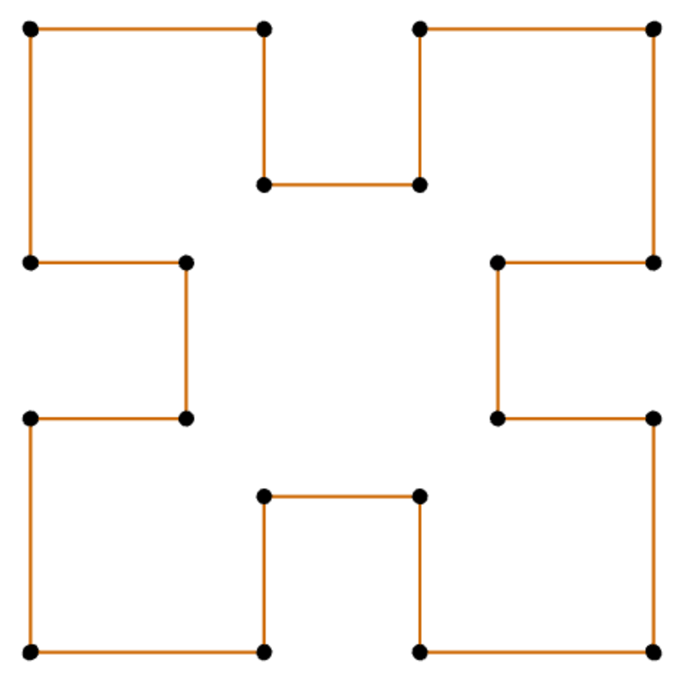
There are a few rules for these challenges:
- You must work with a partner
- You must work at one computer
- Start with a drawing
- Ask us questions
These challenges are opportunities to learn, not measures of your ability. We encourage you to fail and recover, and we are here to help.
Write down any challenges you encounter. We will reflect on them together.
Dowel
Let’s move on to a new solidifier: dowel. We will trace out a spring algorithmically, and then thicken the line into a solid with dowel.
We start by tracing out a circle, approximated first by a hexagon:
moveto 0, 0

repeat 6
  move 1
  yaw 60
end
What if we wanted an octagon instead? What would we need to change?
moveto 0, 0

repeat 8 -- the number of iterations
  move 1
  yaw 45 -- the angle of turning
end
What if we wanted a pentagon? Or a decagon? We might as well write the code for an arbitrary n-gon. We can use variables to express such parametric designs:
n = 10
angle = 360 / n
moveto 0, 0

repeat n
  move 1
  yaw angle
end
Can you see a spring here? Maybe a compressed one. Let’s decompress it a bit by turning not just right but also down. The pitch command works for this, but so does roll:
n = 36
angle = 360 / n
moveto 0, 0

repeat n
  move 0.4
  yaw angle
  roll 1
end
Now, what would we do to get multiple coils? We need to increase the number of circles, which we can do by multiplying the number of iterations:
n = 36
angle = 360 / n
moveto 0, 0

repeat n * 5
  move 0.4
  yaw angle
  roll 1
end
Finally, we thicken it with the dowel command:
n = 36
angle = 360 / n
moveto 0, 0

repeat n * 5
  move 0.4
  yaw angle
  roll 1
end

dowel
Dowel Challenge
Your challenge is to pick one of the following mathematical knots and thicken it into a dowel:
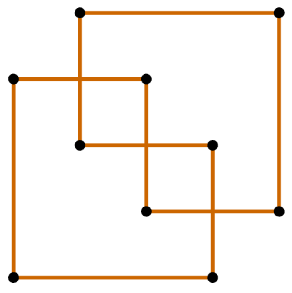
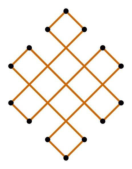
After you get this working, add a parameter to your dowel command to smooth out the corners:
dowel 5
This is the maxBend parameter. It forces the yaw to turn gradually, in 5-degree steps rather than all at once. By default, maxBend is set to 360, meaning that any possible bend between segments will be immediate and not distributed out in steps.
Write down any challenges you encounter. We will reflect on them together.
Revolve
Our third class of solids are surfaces of revolution, which are radially symmetric. We trace out a cross section of the solid, and then revolve it around some axis. Let’s see an example inspired by El Castillo, a Mayan temple in Mexico.

Let’s start our path at the top of the template and wind our way down to the base:
moveto 0, 0
yaw 90

repeat 10
  move 1
  yaw 90
end
This produces a stair-step pattern. If we revolve this around the y-axis, we see a crude approximation of the temple:
moveto 0, 0
yaw 90

repeat 10
  move 1
  yaw 90
end

revolve 0, 1, 0, 360
When we examine the bottom of the temple, we discover it has no bottom. To seal it up, we add a final line segment that returns to the y-axis:
moveto 0, 0
yaw 90

repeat 10
  move 1
  yaw 90
end

yaw 180
move 10

revolve 0, 1, 0, 360
We can increase the number of sides via the special variable nsides:
nsides = 6
This line needs to appear before the revolve to have any effect.
Revolve Challenge
Your challenge for revolve is to model a calamari ring.

Think about its cross section. What would it look if you cut through the ring? Draw it on paper first, and then code it.
Write down any challenges you encounter. We will reflect on them together.
Functions
A lot of introductory programming tools focus on a single computational idea: sequence. Our students are inundated with “Logo puzzlers,” which make them very good movers and turners. But they miss out on deeper computational ideas if that’s all they see. We “turn” now to one of those deeper ideas: procedural abstraction via functions.
Just as variables name data, functions name code. They hide away or abstract a complex sequence of instructions under a short and meaningful descriptor. Let’s see an occasion where the benefit of functions is clear: modeling a paperclip.
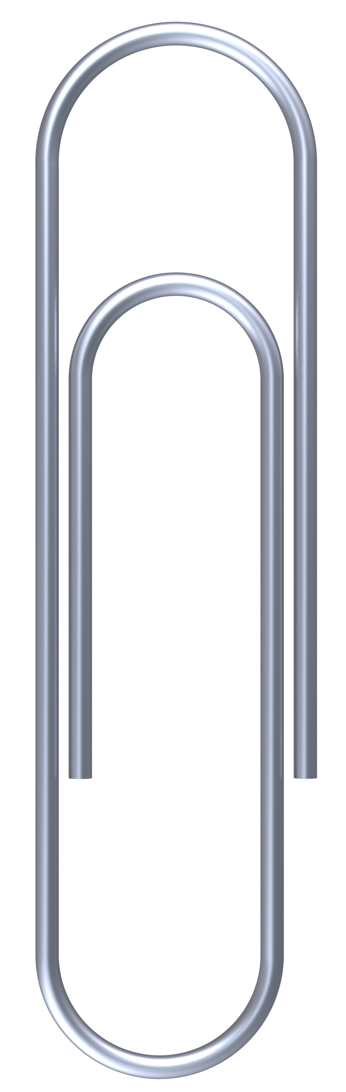
Imagine walking one of these with move and yaw. What would that look like? Let’s work through that traversal. Let’s start at the inner endpoint. We move straight, and then we do the yaw-move shuffle in a semicircle:
moveto 0, 0

move 10
repeat 18
  yaw 10
  move 0.5
end
What happens next? We move straight, and then we do a yaw-move shuffle, but this time with bigger steps:
moveto 0, 0

move 10
repeat 18
  yaw 10
  move 0.5
end

move 14
repeat 18
  yaw 10
  move 0.6
end
What happens next? We move straight, and then we do a yaw-move shuffle, but this time with bigger steps:
moveto 0, 0

move 10
repeat 18
  yaw 10
  move 0.5
end

move 14
repeat 18
  yaw 10
  move 0.6
end

move 19
repeat 18
  yaw 10
  move 0.7
end
What happens next? We move straight, but no yaw-move shuffle this time:
moveto 0, 0

move 10
repeat 18
  yaw 10
  move 0.5
end

move 14
repeat 18
  yaw 10
  move 0.6
end

move 19
repeat 18
  yaw 10
  move 0.7
end

move 14.5

dowel
This code is repetitive. Repetition often begs for a loop, but that won’t cut it here, as the lengths change. Enter functions, which make code reusable and also allow us to leave holes in the algorithm. First, let’s give this repeating pattern of code a name. Since the code draws a straight line and then a bend, I will name it crook:
to crook
  move 10
  repeat 18
    yaw 10
    move 0.5
  end
end
What would two crooks in sequence make?
To allow the lengths to change, we replace the literal numbers with variables:
to crook
  move straightLength
  repeat 18
    yaw 10
    move bendLength
  end
end
And then we must also announce that these variables will be provided when the function is called:
to crook straightLength, bendLength
  move straightLength
  repeat 18
    yaw 10
    move bendLength
  end
end
In defining a function, we add a new recipe to recipe book. To turn a recipe into food, we must follow it, plugging in the ingredients that we provide. To turn a function into executed code, we must call it, plugging in the data that we provide. And we can execute it multiple times, providing different data each time:
to crook straightLength, bendLength
  move straightLength
  repeat 18
    yaw 10
    move bendLength
  end
end

moveto 0, 0
crook 10, 0.5
crook 14, 0.6
crook 19, 0.7
move 14.5

nsides = 40
dowel
Not only is the code much shorter, but we also got a more thrilling cognitive workout as we identified a pattern and abstracted it in a flexible, parametric way.
Functions Challenge
Pac-Man was a very popular arcade game designed by Toru Iwatani in Japan. There’s a maze with lots of little pellets in it. 240 to be exact. There’s also a little yellow circle with a mouth that goes around and eats all the pellets. That’s Pac-Man, and you get to control him. Eating pellets is pretty easy, so what makes the game challenging? Ghosts. If Pac-Man touches one of them, he loses a life.
To get good at Pac-Man, you must get good at moving around in space. And that’s our job in Madeup too. So, to celebrate the importance of space in both Pac-Man and Madeup, we will create a Pac-Man ghost in Madeup.
Observe Blinky
There are actually four ghosts in Pac-Man, and they each behave a little differently and are a different color. We will create Blinky, the red ghost. He’s the lead, and he’s the only ghost who was programmed to actively chase Pac-Man.

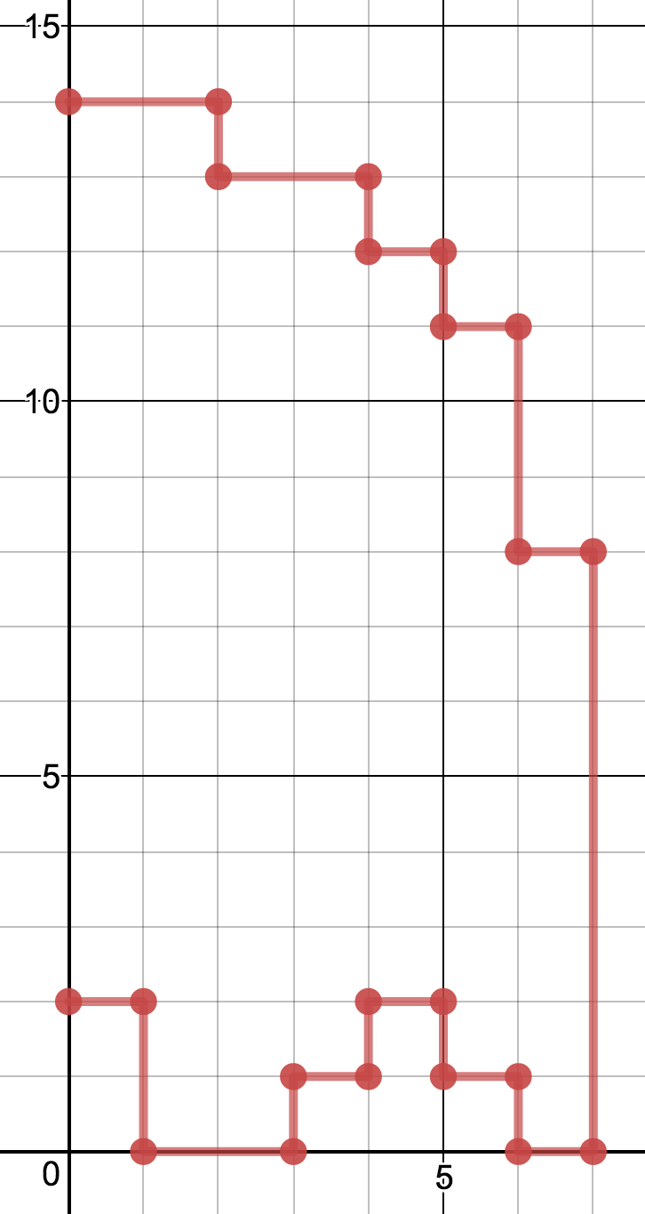
Eventually we are going to write code, but we should always place viscera before computer. We will first draw Blinky. Each of his pixels should be one cell on your graph paper. Ignore his eyes for today.
Since Blinky is symmetric, we only have to draw one half of his body. On the graph paper that we provide, draw only the right half of Blinky:
Measure Blinky
What are the coordinates of Blinky’s top-most vertex?
Compare your answer to mine.
That’s the only vertex whose exact coordinates we’ll need when we start coding.
Now, consider the topmost line segment of Blinky’s body.
How long is it?
Write the segment’s length down next to it. Then go on to the next line segment, measure it, and write down its length. Do this for all the lines of his perimeter. There are 21 segments in all.
Compare your list to mine.
Program Blinky, First Draft
Now that we’ve got all of Blinky’s measurements taken, let’s use Madeup to trace out his outline. Start on the top with a moveto using the xy-coordinates you found earlier. After that, use only moves and yaws to wind around his perimeter, stopping at the bottom.
Once you’ve got his right half, add his left half automatically with this mirror command:
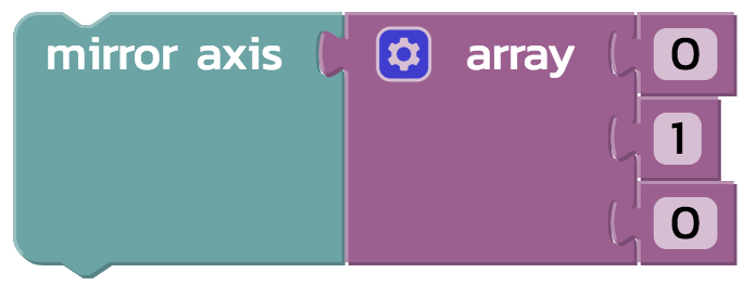
Finally, extrude Blinky to produce a solid model.
Program Blinky, Second Draft
If you look at your program, you’ll see that it is annoying long. We can simplify it with functions. What repeated unit or units of work do you see that would be good candidates for parametric abstraction?
Let’s compare answers.
Maybe you saw something different than what I saw. Whatever you saw, your challenge is to write a function or two to simplify the code you wrote for your first draft.
Write down any challenges you encounter. We will reflect on them together.
Conclusion
If you finish the challenges early, I encourage you to take creative ownership. Design some interesting algorithmic shape. I want to see it!
That’s an introduction to Madeup in two hours. It’s my attempt to provide a spatial context for introducing computer science and mathematics, one that has a connection to the physical world. I have found it useful as a professor of computer science, a father of four, and a volunteer in schools. If you find it useful to support your mission, I encourage us to keep in touch through Twitter, email, or this blog.
Madeup is a labor of love. I am not in the educational technology market and never wish to be. Madeup is an open-source project and has a lot of bugs. If you find one, I’m probably aware of it and am just waiting for the term to finish, but feel free to let me know anyway.
]]>Deprecated: Creation of dynamic property WP_Term::$cat_ID is deprecated in /var/www/twodee/blog/wp-includes/category.php on line 378
Deprecated: Creation of dynamic property WP_Term::$category_count is deprecated in /var/www/twodee/blog/wp-includes/category.php on line 379
Deprecated: Creation of dynamic property WP_Term::$category_description is deprecated in /var/www/twodee/blog/wp-includes/category.php on line 380
Deprecated: Creation of dynamic property WP_Term::$cat_name is deprecated in /var/www/twodee/blog/wp-includes/category.php on line 381
Deprecated: Creation of dynamic property WP_Term::$category_nicename is deprecated in /var/www/twodee/blog/wp-includes/category.php on line 382
Deprecated: Creation of dynamic property WP_Term::$category_parent is deprecated in /var/www/twodee/blog/wp-includes/category.php on line 383
Deprecated: Creation of dynamic property WP_Term::$cat_ID is deprecated in /var/www/twodee/blog/wp-includes/category.php on line 378
Deprecated: Creation of dynamic property WP_Term::$category_count is deprecated in /var/www/twodee/blog/wp-includes/category.php on line 379
Deprecated: Creation of dynamic property WP_Term::$category_description is deprecated in /var/www/twodee/blog/wp-includes/category.php on line 380
Deprecated: Creation of dynamic property WP_Term::$cat_name is deprecated in /var/www/twodee/blog/wp-includes/category.php on line 381
Deprecated: Creation of dynamic property WP_Term::$category_nicename is deprecated in /var/www/twodee/blog/wp-includes/category.php on line 382
Deprecated: Creation of dynamic property WP_Term::$category_parent is deprecated in /var/www/twodee/blog/wp-includes/category.php on line 383
Suppose a man born blind, and now adult, and taught by his touch to distinguish between a cube and a sphere of the same metal, and nighly of the same bigness, so as to tell, when he felt one and the other, which is the cube, which is the sphere. Suppose then the cube and the sphere placed on a table, and the blind man made to see: query, Whether by his sight, before he touched them, he could now distinguish and tell which is the globe, which the cube?
This question is hard to investigate empirically. Hard questions are thrown to the philosophers. For this particular question, the philosopher must consider whether knowledge acquired through one sense can be reactivated through another.
I’m working on a project that has us “sensing” shapes in a different way. In Madeup, we fabricate shapes with code. We sense their parametric qualities and their constraints in an active way. Molyneaux’s question makes me wonder: if we have only programmed shapes and considered them as artifacts produced by computation, would we recognize them if we saw them uncomputationally, with our eyes?
While I find this question intriguing, the truth is that many of us can both see and feel, and much of our experiential knowledge is a combination of sensory inputs. Our eyes see glowing red metal, and we dare not touch it because of what happened last time. We reach into our pockets and feel a metal disc, and our visual cortex assembles an image of a quarter even before it’s visible.
Is fabricating shapes a third way of sensing them? If so, what kind of new knowledge do we gain by having this additional sense? How does this third sense associate with and trigger the other two?
]]>Deprecated: Creation of dynamic property WP_Term::$cat_ID is deprecated in /var/www/twodee/blog/wp-includes/category.php on line 378
Deprecated: Creation of dynamic property WP_Term::$category_count is deprecated in /var/www/twodee/blog/wp-includes/category.php on line 379
Deprecated: Creation of dynamic property WP_Term::$category_description is deprecated in /var/www/twodee/blog/wp-includes/category.php on line 380
Deprecated: Creation of dynamic property WP_Term::$cat_name is deprecated in /var/www/twodee/blog/wp-includes/category.php on line 381
Deprecated: Creation of dynamic property WP_Term::$category_nicename is deprecated in /var/www/twodee/blog/wp-includes/category.php on line 382
Deprecated: Creation of dynamic property WP_Term::$category_parent is deprecated in /var/www/twodee/blog/wp-includes/category.php on line 383
Deprecated: Creation of dynamic property WP_Term::$cat_ID is deprecated in /var/www/twodee/blog/wp-includes/category.php on line 378
Deprecated: Creation of dynamic property WP_Term::$category_count is deprecated in /var/www/twodee/blog/wp-includes/category.php on line 379
Deprecated: Creation of dynamic property WP_Term::$category_description is deprecated in /var/www/twodee/blog/wp-includes/category.php on line 380
Deprecated: Creation of dynamic property WP_Term::$cat_name is deprecated in /var/www/twodee/blog/wp-includes/category.php on line 381
Deprecated: Creation of dynamic property WP_Term::$category_nicename is deprecated in /var/www/twodee/blog/wp-includes/category.php on line 382
Deprecated: Creation of dynamic property WP_Term::$category_parent is deprecated in /var/www/twodee/blog/wp-includes/category.php on line 383
So, I stole them. Well, I stole the idea of them. Andy still has his rings. I took the stolen idea, went to Madeup, and coded up the rings.
I started with a function that generated a spherical shell, a larger sphere with a slightly smaller sphere subtracted away from it:
You can’t tell it’s hollow unless you switch to wireframe.
Then I added two more spherical shells. You won’t be able to see those either, since they’re concentric, so I won’t share that step. But then I added two square dowels around the top and bottom of these spheres:
These dowels overlapped the sections of the spheres I did not want. So I subtracted them:
And I had my rings. They rotate independently:

Now I just need to get these printed in stainless steel. Or gold, with which I could pay back Andy.
]]>Deprecated: Creation of dynamic property WP_Term::$cat_ID is deprecated in /var/www/twodee/blog/wp-includes/category.php on line 378
Deprecated: Creation of dynamic property WP_Term::$category_count is deprecated in /var/www/twodee/blog/wp-includes/category.php on line 379
Deprecated: Creation of dynamic property WP_Term::$category_description is deprecated in /var/www/twodee/blog/wp-includes/category.php on line 380
Deprecated: Creation of dynamic property WP_Term::$cat_name is deprecated in /var/www/twodee/blog/wp-includes/category.php on line 381
Deprecated: Creation of dynamic property WP_Term::$category_nicename is deprecated in /var/www/twodee/blog/wp-includes/category.php on line 382
Deprecated: Creation of dynamic property WP_Term::$category_parent is deprecated in /var/www/twodee/blog/wp-includes/category.php on line 383
Deprecated: Creation of dynamic property WP_Term::$cat_ID is deprecated in /var/www/twodee/blog/wp-includes/category.php on line 378
Deprecated: Creation of dynamic property WP_Term::$category_count is deprecated in /var/www/twodee/blog/wp-includes/category.php on line 379
Deprecated: Creation of dynamic property WP_Term::$category_description is deprecated in /var/www/twodee/blog/wp-includes/category.php on line 380
Deprecated: Creation of dynamic property WP_Term::$cat_name is deprecated in /var/www/twodee/blog/wp-includes/category.php on line 381
Deprecated: Creation of dynamic property WP_Term::$category_nicename is deprecated in /var/www/twodee/blog/wp-includes/category.php on line 382
Deprecated: Creation of dynamic property WP_Term::$category_parent is deprecated in /var/www/twodee/blog/wp-includes/category.php on line 383
I wondered if I could “draw” bad stars in Madeup. My first attempt visits the 10 vertices of a star, five for the points and five for the armpits. In a regular star, these vertices occur exactly 36 degrees apart on a circle’s perimeter. To form an irregular star, I visit these angles but perturb them ever so slightly. I also perturb the radius. Here’s the result:
Click the middle button (Solidify) to generate a new star.
]]>