4-pin Buttons on Arduino
At the early stages of learning, we tend to mimic without understanding. That’s how I learned to code, and that’s how I’m learning electronics. A book presents a circuit diagram, and I copy it faithfully. And lo, it works! That small thrill carries me to the next step of understanding.
Here’s a circuit that I mimicked without understanding for a very long time:
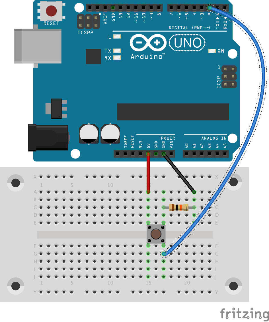
The purpose of this circuit is to be able to read pin 2 on the Arduino, which should read a certain value (HIGH or LOW) when the button is pressed and the opposite value when it’s not pressed. We can do the reading with an Arduino sketch like this:
void setup() {
  pinMode(2, INPUT);
  Serial.begin(9600);
}

void loop() {
  int reading = digitalRead(2);
  Serial.println(reading);
}
But on the hardware side, why is there a resistor? Why are there three wires? How are the electrons flowing through? Compared to other circuits, this looks pretty simple. If I can’t understand this one, then, how can I expect to understand more complex ones? So, here’s my attempt to make sense of this circuit.
Button
Understanding the button’s anatomy is a crucial first step. When a 4-pin button is not pressed, electrons flow only along the vertical axis shown in the diagram. When pressed, electrons flow between all pins. It would seem, then, that this circuit should achieve our purpose:

Indeed, this circuit half-works. When the button is pressed, we see HIGH voltage at pin 2. But when it’s not pressed, we get unpredictable values. When the button’s path to 5V is broken, pin 2 is not really connected to anything. It is said to be floating, which means that voltage readings are essentially coming from random electrical noise that the Arduino picks up. To prevent floating, we need to anchor pin 2 to ground—but only when the button’s not pressed.
No Floating
Recall that electrons flow vertically when our button is not pressed. Therefore, our first attempt to unfloat pin 2 might be this:

This circuit also half-works, but in the opposite way. When the button’s not pressed, pin 2 reliably reads LOW. But we’ve changed what happens when the button is pressed. Recall that all pins of the button become connected when it’s pressed. That means there will be a path from 5V to ground. Since there’s no load on this path, we have a short circuit, and the fire trucks are on their way.
No Short Circuit
The fix to the short circuit is to discourage electrons flowing from ground to 5V with a resistor. We could put it on the ground side of the circuit, which leads us to the circuit that started our discussion:
When the button’s pressed, pin 2 is connected to 5V and reads HIGH. When it’s not pressed, pin 2 is connected to ground and reads LOW. We say it has been pulled low by a pulldown resistor.
Pullup
Alternatively, we could put the resistor on the 5V side and connect pin 2 to 5V to produce a pullup resistor:
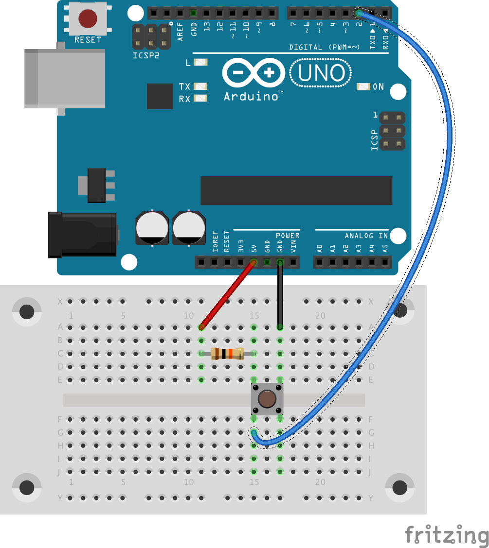
When the button’s pressed, pin 2 is connected to ground and reads LOW. When it’s not pressed, pin 2 is connected to 5V and reads HIGH. This is the exact opposite of the pulldown resistor.
Personally, I feel like the terms pullup resistor and pulldown resistor give too much credit to the resistor. The real reason for the up and down of the voltage is the side of the button we can connect the load to, not the resistor. The resistor gets dropped in where it does as a consequence of the arrangement we choose.