Chorder, Part I
This post is part of a series of notes and exercises for a summer camp on making musical instruments with Arduino and Pure Data.
It’s time to assemble our instrument that plays chords. Let’s call it the chorder! What hardware shall we use for input? We’ve already used buttons, and we’ve already used potentiometers. We haven’t used fruits and vegetables yet, so let’s give them a turn.
Capacitors
You wouldn’t normally think of a tomato as an electronic component. But a tomato can act as a capacitor, a component in an electric circuit that can store up electricity and release it later. Most other components pass their electrons through immediately, but the capacitor is different. It hoards. It banks. It capacitates.
When a human finger touches a tomato-capacitor, the electricity stored within in it discharges along the circuit. We’ll exploit this phenomenon in the hardware for our chorder. Don’t worry. The electricity doesn’t actually pass through your hand.
Hardware
The baseline chorder will play the seven major chords of a scale, so we will need seven capacitors. To plug all of these into our circuit, we’ll use a 12-touch capacitance sensor—an MPR121 from Adafruit. The hardware looks like this:
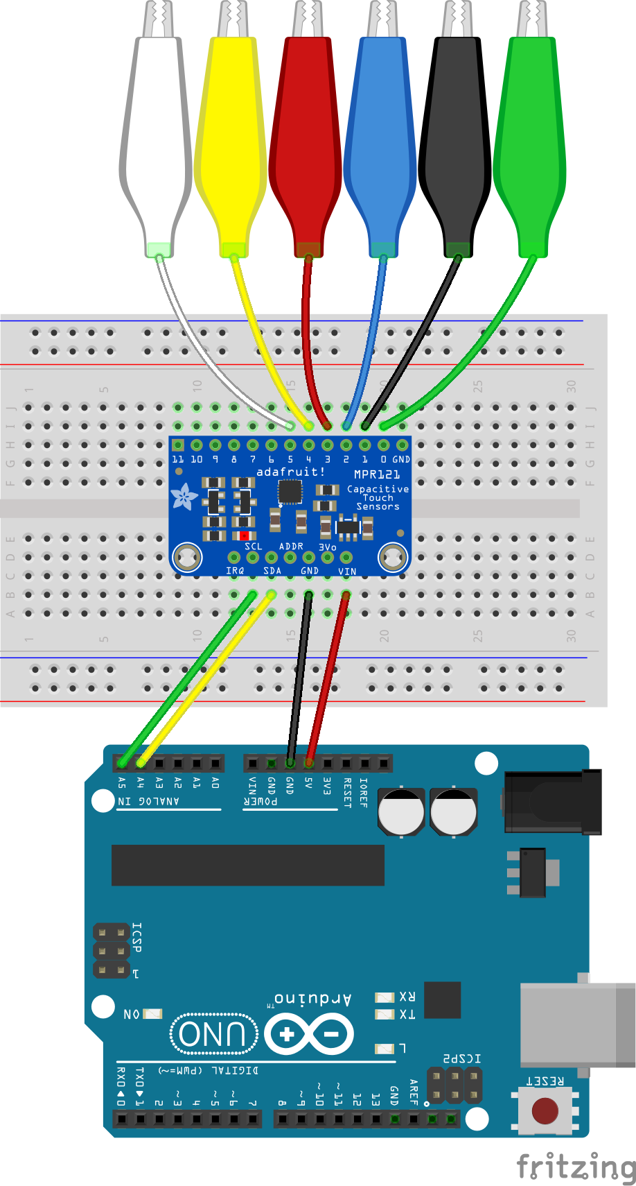
Go ahead and assemble your chorder. The voltage and ground connections behave the same way as they did in our other instruments. Pins 0 and beyond on the capacitance sensor connect to our fruits and vegetables via alligator clips. There are only six in the diagram, because there were only six different colors of clips available in the circuit drawing tool. Use seven in your actual circuit.
The wires going from SCL to A5 and from SDA to A4 are new. This sensor uses a standard electronic protocol called I2C. This protocol describes how a boss device can control a bunch of servant devices with just two wires, which have the following roles:
- The boss device (the Arduino) sends a periodic electrical signal along the Serial CLock pin. This pulse serves as the heartbeat of the circuit; all servants synchronize their operations to it.
- The boss and servants send messages back and forth along the Serial DAta wire. In our case, when a capacitor discharges, a signal will be sent along the SDA pin.
Arduino speaks the I2C protocol on pins A4 and A5.
Firmware
We will test our hardware with the smallest program we can write that shows the sensor is working. To handle the business of talking to the capacitor, we’ll use a helper library from Adafruit. Follow these steps to get it installed:
- Open the Arduino IDE.
- Navigate to Sketch / Include Library / Manage Libraries.
- Search for Adafruit MPR121.
- Select the matching result.
- Click Install.
Now create a new Arduino sketch. Insert this line at the top of your file to make the Adafruit code available:
#include "Adafruit_MPR121.h"
Right before setup, declare and initialize a global variable that models the capacitor:
Adafruit_MPR121 sensor = Adafruit_MPR121();
The type Adafruit_MPR121 is defined in the helper library.
In setup, start up the Serial port just like we’ve done in the past. But we also want to initialize the sensor with this line:
sensor.begin(0x5A);
That 0x5A is a base-16 number that identifies the servant device. The boss uses this identifier to direct messages to the right I2C device. If we had a second capacitance sensor in our circuit, we’d need to pass a different identifier. Otherwise they’d get each other’s mail.
In loop, we can get an integer that tells us the state of all 12 capacitors using the touched function. It returns an 16-bit integer (a short) that we can print:
short bits = sensor.touched();
Serial.println(bits);
Upload your program, open the Serial Monitor, and touch the alligator clips with your hands. Does the output change?
Challenges
After you get the chorder hardware set up, answer the following questions on a piece of scratch paper.
- What clips must you touch to produce the number 37?
- The base-10 output from the code above is not very intuitive. When you see the number 53, it takes you a while to figure out that pins 5, 4, 2, and 0 are being touched. Investigate the documentation for Arduino’s
Serial.printlnfunction. Change your code to print in base-2 or binary. What change did you make? - Your change in the previous challenge improved things, but the output was ragged. The numbers had different lengths, depending on the number of clips that were being touched. Any leading zeroes on the binary presentation of the number were not printed. It’d be better if we saw output like this when pins 5, 4, 2, and 0 were touched:
000000110101
There’s no builtin function in Arduino to do this, but we can write our own. Follow these steps:- Write a function named
printBitsthat accepts ashortparameter for your bitfield. - In the function, write a
forloop that counts from 11 through 0. - On each iteration i, retrieve bit i from the bitfield using the builtin
bitReadfunction. - Print each bit using
Serial.print. - After the loop finishes, print a blank line with
Serial.println(""). - Call
printBitsinloopinstead ofSerial.println.
- Write a function named