Music Mouse, Part I
This post is part of a series of notes and exercises for a summer camp on making musical instruments with Arduino and Pure Data.
First order of business: switch partners. Choose a partner that you haven’t worked with yet.
Our final instrument is inspired by the work of composer Laurie Spiegel. In particular, we will recreate her instrument the Music Mouse. This software was released in the 1980s. In the manual for this software, Spiegel addresses the concerns that some musicians may have about technology:
I firmly believe that logic, when used well, does not conflict with intuition, emotion, or other aspects of music which are often considered contrary to it. Rather than constraining musicality, logical structures can serve to support, extend, and amplify our ability to express and embody the undefinable qualities of aesthetic meaning which we are forever trying to capture.
These same ideas apply to us. We use machines to carry out our dreams! We are not interested in reducing our humanity in any way.
Music Mouse
To get a feel for what we’ll be doing in this exercise, play Tero Parviainen’s implementation of the Music Mouse.
The Music Mouse allows the musician to traverse a two-dimensional landscape. Move on one axis to produce a melody, move on the other to produce harmony. By default, the harmony is played in the form of major chords.
Hardware
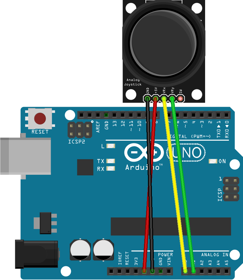
To allow musicians to walk a two-dimensional space, we will use a joystick. Our circuit looks something like this:

The joystick has five pins. The ground and voltage pins behave the same as they did with our other components. The VRX and VRY pins are both analog and they report the direction in which the joystick is pushed. The joystick can also be pushed down, and the SW pin reports the state of this push button.
Build your circuit. You probably don’t need a breadboard. You can also leave the SW pin disconnected. We won’t be using the button in this exercise.
Firmware
Let’s write the simplest possible Arduino program to test our circuit. Follow these steps:
- In
setup, prepare pins A0 and A1 forINPUTand set up the serial port. - In
loop, read the pins withanalogReadand print the results. - Print a blank link after the two numbers so you can more easily read the output.
- Add a slight delay to slow down the stream of output.
Upload your code. You should see numbers fly in the Serial Monitor. Make sure each axis works.